


Temperature widget in AsicBoost firmware
Chip and board temperature: how to read the numbers
The widget shows two ranges: chips and PCB. Below are the marks where you should step in, and why S19 and S21 measure it differently.
The large white numbers are chip temperature, from the lowest to the highest across all boards. The small grey numbers below are the laminate temperature, the PCB. The difference between them is usually 10 to 15 degrees, and that is a normal offset, not a broken sensor.
| Chip temperature | What to do |
|---|---|
| 60 to 65 °C | A good place to be, the default target is 65 °C |
| around 70 °C | Acceptable, in summer it is the usual picture |
| 75 °C and above | Time to check the cooling and drop the profile |
| 85 to 90 °C | Fast chip degradation, the protection stops the ASIC at 90 °C |
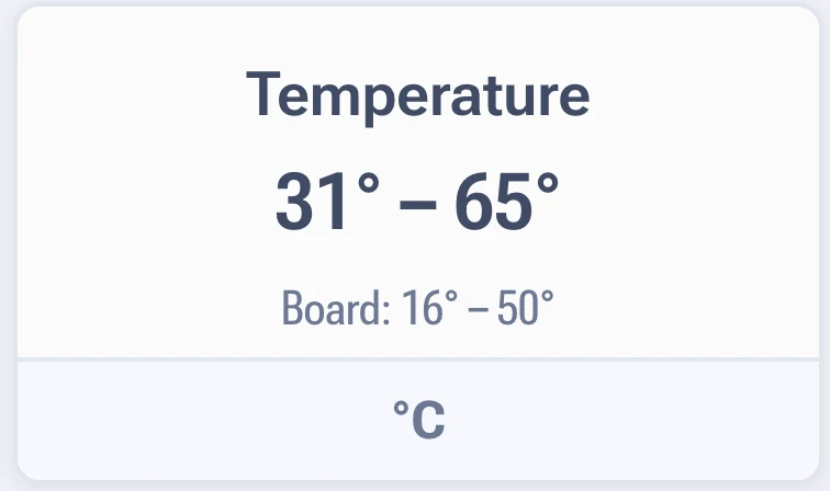
The spread matters more than the maximum
A single maximum tells you little. Look at how wide the range is. A spread of up to 8 degrees between the coldest and the hottest chip is normal for air cooling. A spread of 15 degrees or more means uneven airflow, a sloppy layer of thermal paste or a dried out pad.
On hydro versions the protection is tied to the spread: the ASIC will not start if the difference between the highest and the lowest chip temperature is more than 10 degrees, if the maximum is above 60 °C or if the temperature is below 20 °C. More on that in the section on cooling.
Where the reading comes from
- S19 series. The control board polls sensors on the hash boards over the I2C bus, wired to the pins of certain chips. So the reading does not come from every chip.
- S21 series, plus L9 and T21. Temperature is read from each chip individually. That is why the range in the widget is wider, and why there is a separate option to ignore faulty chip sensors in the advanced settings.